Slide :
Friday, April 22, 2011
Thursday, April 21, 2011
Ping Pong Ball Target System
 |
| Figure 1, Ping Pong Robot |
Member Names (with emails)
KoTung Lin (kevinlin [at] umich.edu)
Daniel Cheng (udx [at] umich.edu)
Brief Project Description
Our goal is to implement the the inverse kinematic and forward kinematic for the ping pong ball robot and make the ping pong reaching the entire workspace. We will attempt to achieve the following: ground target aiming, trajectory planning for singularity prevention and integrate with the GUI operation panel for with trajectory prediction.
Objectives
- Forward kinematic
- Inverse kinematic
- Singularity prevention
- Graphic User Interface
- Trajectory prediction and projection to the alternative camera view point

Graphical User Interface (GUI)r
The GUI interface is designed to implement forward (FK) and inverse (IK) kinematics with ease. The parameters for FK could be entered via text boxes or scroll bar below the 'Plot Theta/Phi' push button. To implement IK, values are entered below the 'Plot XY' push button. To execute FK or IK after value entry, the 'Plot Theta/Phi' and 'Plot XY' buttons are pressed respectively. When values for FK are provided and executed the corresponding XY values would be displayed in the text entry boxes, likewise when XY values are enter for IK the corresponding forward kinematic values of Theta/Phi are calculated and displayed on the entry boxes.
The previous trajectory path are overwritten by new plots. Trajectories could also be manually cleared by 'Clear Plots' push button.
The GUI is design to display the trajectory path of the projectile in the 3rd person perspective behind the pingpong cannon. An background image of the pingpong cannon's testing environment is added to show relative accuracy of the trajectory prediction in a live setting. The Theta and Phi angle therefore correspond to the left/right and up/angles of the barrel aim respectively.
Before initializing the GUI, a background image file would have to be present in the MATLAB code execution coder with corresponding name as the image reader name. When MATLAB code is executed, the image should appear on the plot space area. In order to view the trajectory clearly especially under complex background image conditions, the image could be changed to gray scale or the lines of trajectory could be made thicker.
Note: There is both angle and XY value limitations due to the physical performance of the cannon's actuating servos and solenoid power. The hard limits of Theta/Phi angles are shown at the side of the scroll bars. If values outside the allowable values are entered, the values would be changed to the closest permissible value. The limit for XY values are scaled to 10.
Final Exam Question
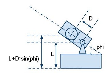
 |
| Figure 1, robot parameter |
 |
| Figure 2, robot parameter |
The transformation from Cartesian coordinate to Cylindrical coordinate is

According to the equation we derived from Newton's Law of Motion,

and the flight time equation,

The range of the ball will be at

Now , suppose we have a addition actuator for ping pong ball robot to control the initial velocity Vo. Under the Cylindrical coordinate (r, theta) , what will be the new corresponding Jacobian Matrix for the falling spot of the ball? Where the form of Jacobian will be like

Solution
Since

the new Jacobian Matrix will be


So, the overall Jacobian matrix will look like

Wednesday, April 20, 2011
Progress - April, 19
The ping pong ball fall out problem is solved by using another initial condition. If we apply 90 degree (vertical position) as initial value of angle. Then it won't be a problem.
But then the robot will be start in the singular configuration, so we increase make the judgment of near singular more strict, to ensure the inverse kinematic works well
But then the robot will be start in the singular configuration, so we increase make the judgment of near singular more strict, to ensure the inverse kinematic works well
Saturday, April 16, 2011
Progress - April, 16
After finish all the code and simulation on the MATLAB, we start to integrate the program with the robot.
The first issue we are dealing is using MATLAB to connect with robot. Previously, the program structure didn't include the GUI part, so it works well. But after the GUI part is combined, where should we placed the connection code to prevent the frequent COM port connection for causing the program crash. Eventually, we place the port connection in the background drawing subroutine, and it works just fine. After the connection is done, the rest of work would be insert the motor control function in to each corresponding button.
New problem:
- The inverse kinematic works well, but we neglect that ping pong ball will fall out if the barrel angle Phi is less than 0. Solving the inverse kinematic with integral Jacobian matrix will converge only to the nearest solution. Therefore, we need to find a alternative solution for fixing this situation.
- The trajectory projection function works fine, but the problem is to express it with a better way. This also need to be fixed.
- Parameter adjusting
- lambda for the depth of view
- initial velocity of ping pong ball
- the coordinate scaling for task space to background picture.
Subscribe to:
Posts (Atom)